


Inverter, as a crucial component of the entire power station, is placed above the DC components and below the grid-connected devices. It can detect almost all parameters of the power station. In case of anomalies, feedback from the inverter can be used to inspect the health status of the station's associated equipment. Below are some common fault information and handling methods for photovoltaic inverters.
No grid connection
Fault cause: Indicates either no connection to the grid or disconnection of the AC breaker, resulting in the inverter not detecting the voltage from the grid.
Solution:
1. Check if the grid is powered off. If so, wait for the grid to restore power.
2. If the grid is powered normally, use a multimeter in AC voltage mode to measure if the AC output voltage is normal. First, measure at the inverter output and check if there are any issues with the inverter output side. If there are no issues, it may be an external AC side circuit interruption. Check the safety switches such as air switches, knife switches, over/under voltage protectors for damage or disconnection.
AC voltage out of range
Fault cause: When photovoltaic power generation is connected to the user-side grid, the voltage at the connection point may rise. The greater the internal resistance of the grid, the greater the rise. The closer to the transformer, the smaller the line resistance and the smaller the grid fluctuation, whereas at the end of the grid, the longer the line, the greater the voltage fluctuation. Therefore, when the inverter is connected to the grid far from the transformer, the working environment of the inverter on the grid becomes poor. If it exceeds the upper limit of the inverter's operating voltage, the inverter will fault and stop working.
Solution:
1. Try to place the connection point of the photovoltaic power station closer to the transformer output to reduce line losses.
2. Shorten the length of the inverter's AC output line as much as possible, or use thicker copper core cables to reduce the voltage difference between the inverter and the grid.
3. Nowadays, most grid-connected inverters have AC voltage regulation functions. Contact the manufacturer to widen the AC voltage range to adapt to grid voltage fluctuations.
4. If possible, adjust the output voltage of the transformer downwards.
Low insulation impedance
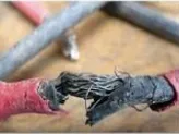
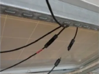
Fault cause: The inverter has the function of detecting the insulation impedance on the DC side. When the positive and negative poles of the DC side are detected to have an impedance lower than 50kΩ, the inverter will report a "PV insulation impedance too low" fault to prevent electric shock danger caused by human contact with energized parts of the panel and the ground simultaneously. Factors affecting this include: leakage of DC components; cable insulation damage, exposed live parts are damp; poor grounding of module supports; excessively high humidity in weather and power station environment, etc.
Solution:
Disconnect the AC and DC circuit breakers, use a dedicated MC4 disassembly wrench to remove the positive and negative poles of the DC measuring group from the DC side to ensure reliable grounding of the module support. Use a multimeter in the megaohm range, with the red probe connected to the positive pole of the group string and the black probe to the ground, to read the impedance of each positive pole to ground. Then connect the red probe to the negative pole of the group string and read the impedance of each negative pole to ground. If it is greater than 50kΩ, it is judged that the string insulation is reliable. If it is less than or equal to 50kΩ, it is judged that there is a problem with the string insulation. You can individually check the cable condition of that string to see if there is any damage or poor contact. Low insulation impedance is generally caused by a short circuit between the positive and negative poles.
High leakage current
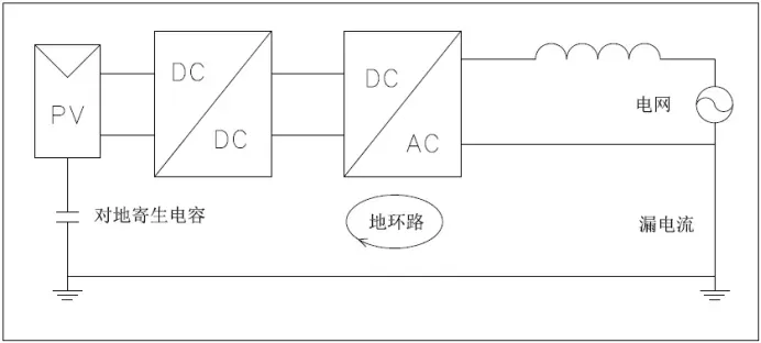
Fault cause: The inverter's leakage current detection module detects excessive leakage current, which stops working to protect personal safety and reports this fault information.
Solution:
1. Disconnect the PV input, restart the machine, and observe if the machine can return to normal.
2. Check if the AC ground wire is connected to the live wire, measure if the voltage between the ground wire and the live wire is normal, or use a leakage current detector for detection.
3. If there is no connection between the ground wire and the live wire, it is likely to be a machine leakage. Contact the manufacturer for assistance.
High DC voltage
Fault cause: Too many components in a single PV string result in a voltage exceeding the PV voltage limit of the inverter.
Solution:
Check the parameters of the inverter, determine the input range of the DC voltage, and then measure whether the open-circuit voltage of the string is within the allowable range of the inverter. If it exceeds the allowable range, reduce the number of components connected in series in the string.
Similarly, if a low PV voltage is reported, check whether the number of components connected in series is too small, or whether the positive and negative poles of the string are connected in reverse, the terminals are loose, the contact is poor, or there is an open circuit in the string.
Inverter screen display failure
Fault cause:
1. No DC input or auxiliary power supply failure. The inverter LCD is powered by DC, and the component voltage does not reach the inverter start voltage.
2. PV input terminals are reversed. The PV terminals have positive and negative poles that must correspond to each other and cannot be connected to other strings in reverse.
3. The DC switch is not closed.
4. One component is disconnected, causing other strings to not work.
Solution:
1. Use a multimeter in voltage mode to measure the DC input voltage of the inverter. When the voltage is normal, the total voltage is the sum of the voltages of each component.
2. If there is no voltage, sequentially check if the DC switch, wiring terminals, cable joints, and components are normal.

Monitoring issues
Fault cause: Lack of communication between the data logger and the inverter; data logger is not powered on; signal issues at the installation location; internal issues with the data logger.
Solution:
1. Check if the communication interface between the data logger and the inverter is normal, and observe the status of the communication indicator lights.
2. Check the signal strength at the local location. If the signal is weak, an enhanced antenna may be needed.
3. Scan the correct serial number of the data logger.
4. Under external conditions without problems, if there is no response from the data logger even with connections, it may be considered an internal fault of the data logger.
In conclusion, the typical problems of inverters in photovoltaic projects have been analyzed, and some suggestions have been provided. Understanding the causes and treatment methods of typical problems is essential. Moreover, in the daily maintenance of the power station, comprehensive safety protection measures and good standard operation and maintenance are also crucial to ensure the profitability of the power station.
If you're interested in learning more about our solar energy storage offerings, we encourage you to explore our product line. We offer a range of panels and battery that are designed for various applications and budgets, so you're sure to find the right solution for your needs.
Website:www.fgreenpv.com
Email:Info@fgreenpv.com
WhatsApp:+86 17311228539
Post time: Apr-14-2024


